

Arduino Nano V3 Pinout
Find the Arduino Nano V3 pinout, digital and analog pins, memory limits, and Circuitera compile/upload support. Check board-specific library compatibility.
- Processor
- ATMEGA328P
- Clock
- 16 MHz
- Physical flash
- 32768 bytes
- Application flash
- 30720 bytes
- SRAM
- 2048 bytes
- EEPROM
- 1024 bytes
- Digital pins
- 14
- Analog inputs
- 8
- PWM
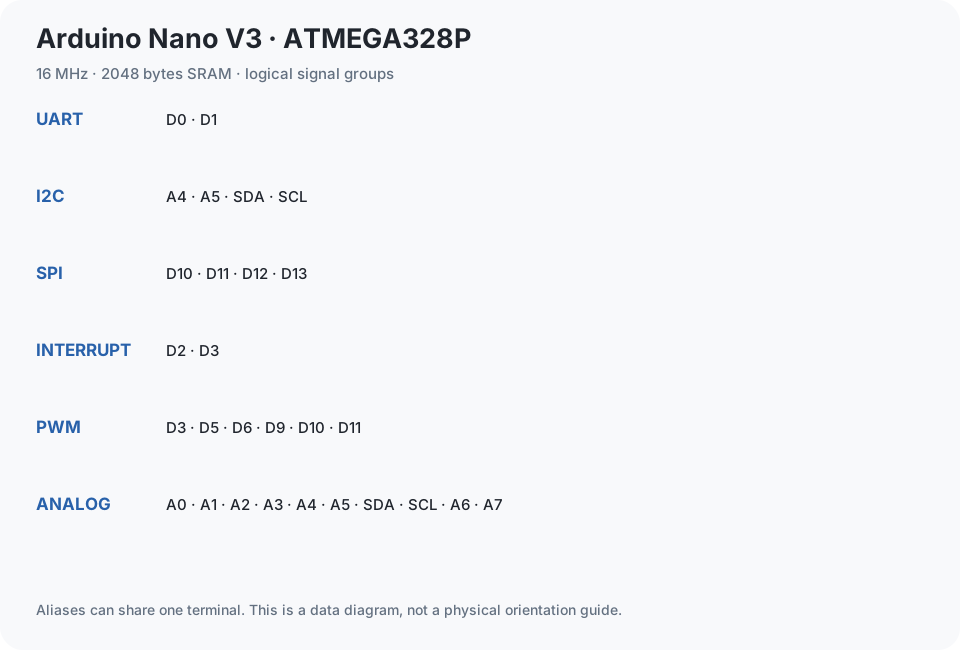
- D3, D5, D6, D9, D10, D11
- Hardware UARTs
- 1
- UART pins
- D0, D1
- I2C
- A4, A5, SDA, SCL
- SPI
- D10, D11, D12, D13
- External interrupts
- D2, D3
- Logic voltage
- 5 V
- Bootloader
- New bootloader · Optiboot
- Protocol / baud
- STK500v1 · 115200
- Compile capability
- Verified · automated compile
- Upload capability
- Untested · physical hardware
- Serial capability
- Untested · physical hardware
- Simulation
- Not supported for this profile
- Build-matched compile check
- 2026-10-25
Choose the correct bootloader
The new Nano bootloader profile uploads at 115200 baud; the old profile uses 57600 baud. Select the profile that matches the bootloader actually installed on your board. If the sketch verifies but the bootloader handshake fails, check this setting along with the cable and port. Changing the profile does not install a different bootloader.
Use Nano-specific analog inputs
The Nano variant includes A0–A7. A6 and A7 are analog-input-only: do not treat them as ordinary digital outputs. I2C uses A4/A5, and PWM follows the ATmega328P pin assignments on D3, D5, D6, D9, D10, and D11. Pin helpers and autocomplete follow the selected board, so select Nano before relying on those hints.
Keep the sketch within memory
Both classic Nano profiles compile for ATmega328P at 16 MHz and provide 30,720 bytes of application flash and 2,048 bytes of SRAM. Large display buffers or long text strings can consume SRAM quickly. Read the build’s static RAM report and leave room for runtime stack and heap use; a successful link does not guarantee that an oversized program will run reliably.
Understand which Nano this covers
Nano Every, Nano 33, and Nano ESP32 are different targets and cannot use this profile. Some classic clones have USB bridges that need host drivers or school administrator approval. Use Serial Monitor to check a simple known-working sketch after upload. The browser cannot bypass operating-system or managed-device restrictions.
Upload and validation limits
Select the actual board and bootloader, use a USB data cable, and grant one port permission. Keep serial pins clear of interfering peripherals.
No physical upload certification recorded in these build reports. Compile capability, simulated protocol tests and physical upload are separate claims.
Toolchain: avr-gcc-wasm@0.2.0. Last matching compile evidence: 2026-10-25. Build: e0f6d304cce4ae0a0989a9b1300cbc1a21a595e5e3e7f57ed0ab3468ecf7940b.
Choose the exact variant
The specifications above use Arduino Nano V3 — ATmega328P (new bootloader). Check the voltage, clock and bootloader for your physical board before connecting an adapter or compiling.
| Profile | Clock | Logic voltage | Bootloader | Upload baud |
|---|---|---|---|---|
| Arduino Nano V3 — ATmega328P (new bootloader) | 16 MHz | 5 V | New bootloader · Optiboot | 115200 |
| Arduino Nano V3 — ATmega328P (old bootloader) | 16 MHz | 5 V | Old bootloader · ATmegaBOOT | 57600 |
Arduino Nano V3 pinout table
Every pin and alias is present in the initial HTML. Filter by signal capability, or select a pin for its existing reference details. Disconnect power before changing wiring.
29 pin entries
Select a pin to read its capabilities.
| Pin | Capabilities | Details |
|---|---|---|
| DIGITAL · UART | RX · shared with the USB serial connection | |
| DIGITAL · UART | TX · shared with the USB serial connection | |
| DIGITAL · INTERRUPT | External interrupt INT0 | |
| DIGITAL · PWM · INTERRUPT | External interrupt INT1 · PWM | |
| DIGITAL | Digital input/output | |
| DIGITAL · PWM | Digital input/output · PWM with analogWrite() | |
| DIGITAL · PWM | Digital input/output · PWM with analogWrite() | |
| DIGITAL | Digital input/output | |
| DIGITAL | Digital input/output | |
| DIGITAL · PWM | Digital input/output · PWM with analogWrite() | |
| DIGITAL · PWM · SPI | SS · SPI chip select | |
| DIGITAL · PWM · SPI | MOSI · SPI data to peripherals | |
| DIGITAL · SPI | MISO · SPI data from peripherals | |
| DIGITAL · SPI | SCK · also connected to the onboard LED | |
| ANALOG · DIGITAL | 10-bit analog input (0–1023). Also digital pin 14. | |
| ANALOG · DIGITAL | 10-bit analog input (0–1023). Also digital pin 15. | |
| ANALOG · DIGITAL | 10-bit analog input (0–1023). Also digital pin 16. | |
| ANALOG · DIGITAL | 10-bit analog input (0–1023). Also digital pin 17. | |
| ANALOG · DIGITAL · I2C | 10-bit analog input (0–1023). Also digital pin 18. SDA · same signal as SDA. | |
| ANALOG · DIGITAL · I2C | 10-bit analog input (0–1023). Also digital pin 19. SCL · same signal as SCL. | |
| POWER | 5 V power rail, not a programmable I/O pin. | |
| POWER | 3.3 V output from the USB interface where fitted. Availability and current limit depend on the Nano-compatible board. Not a programmable pin. | |
| GROUND | Common ground reference. Join the ground of connected modules to GND. | |
| POWER | External power input before the regulator. For first projects, power the Nano through USB. | |
| RESET | Pulling RESET low restarts the microcontroller. The reset button does the same. | |
| I2C · DIGITAL · ANALOG | I2C data. Electrically the same pin as A4, not an extra independent pin. | |
| I2C · DIGITAL · ANALOG | I2C clock. Electrically the same pin as A5, not an extra independent pin. | |
| ANALOG | 10-bit analog input (0–1023), analog-only. Use analogRead(). This pin cannot use digitalRead(), digitalWrite(), pinMode() or PWM. | |
| ANALOG | 10-bit analog input (0–1023), analog-only. Use analogRead(). This pin cannot use digitalRead(), digitalWrite(), pinMode() or PWM. |
Library compile results
Actual source/hash-matched results for this exact profile. A passed compile does not prove a real peripheral, motor or wiring works.
| Library | Pinned version | Result | Flash / static RAM | Test date |
|---|---|---|---|---|
| HID | 1.0 | UNSUPPORTED | Not recorded | 2026-10-25 |
| Keyboard | 1.0.7 | UNSUPPORTED | Not recorded | 2026-10-25 |
| Mouse | 1.0.1 | UNSUPPORTED | Not recorded | 2026-10-25 |
| Servo | 1.3.0 | PASS | 2522 / 50 bytes | 2026-10-25 |
| Wire | 1.0 | PASS | 4494 / 408 bytes | 2026-10-25 |
| SPI | 1.0 | PASS | 2728 / 192 bytes | 2026-10-25 |
| EEPROM | 2.0 | PASS | 2424 / 188 bytes | 2026-10-25 |
| SoftwareSerial | 1.0 | PASS | 3466 / 301 bytes | 2026-10-25 |
| LiquidCrystal | 1.0.7 | PASS | 2232 / 59 bytes | 2026-10-25 |
| DHT | 1.4.7 | PASS | 5610 / 219 bytes | 2026-10-25 |
| Adafruit Unified Sensor | 1.1.15 | PASS | 9226 / 302 bytes | 2026-10-25 |
| Adafruit GFX | 1.12.6 | PASS | 10952 / 533 bytes | 2026-10-25 |
| Adafruit SSD1306 | 2.5.17 | PASS | 13868 / 399 bytes | 2026-10-25 |
| Adafruit BusIO | 1.17.4 | PASS | 7140 / 438 bytes | 2026-10-25 |
| Adafruit NeoPixel | 1.15.5 | PASS | 3270 / 41 bytes | 2026-10-25 |
| NewPing | 1.9.7 | PASS | 3304 / 209 bytes | 2026-10-25 |
| IRremote | 4.7.1 | PASS | 12096 / 491 bytes | 2026-10-25 |
| Keypad | 3.1.1 | PASS | 3922 / 327 bytes | 2026-10-25 |
| AccelStepper | 1.64 | PASS | 6118 / 119 bytes | 2026-10-25 |
| LiquidCrystal_I2C | 1.1.2 | PASS | 4006 / 275 bytes | 2026-10-25 |
Projects and next steps
The public tutorials are validated on Uno. Their concepts can help with this board, but wiring, pin maps, libraries and the exact profile must be reviewed and verified separately; they are not claimed as tested projects on this board.