

Tested with Circuitera 1.0.0: the article’s complete C++ sketch compiled for Arduino Uno R3 using avr-gcc-wasm@0.2.0 on 2026-10-31 (UTC). No modeled execution is claimed for this article. No physical board was tested.
A button-controlled counter sometimes advances twice for one press. Slowing the whole program with delay() appears to help, until a short press is missed or another part of the project stops responding. The missing idea is an accepted event: the program needs to decide which electrical transitions represent one physical action.
A pull-up resistor establishes the released level. It does not guarantee that mechanical contacts make one clean transition. If the raw circuit is unfamiliar, read the existing INPUT_PULLUP explanation first. This article starts after that wiring works and concentrates on turning the sampled signal into deliberate press events.
Separate three states in your notes
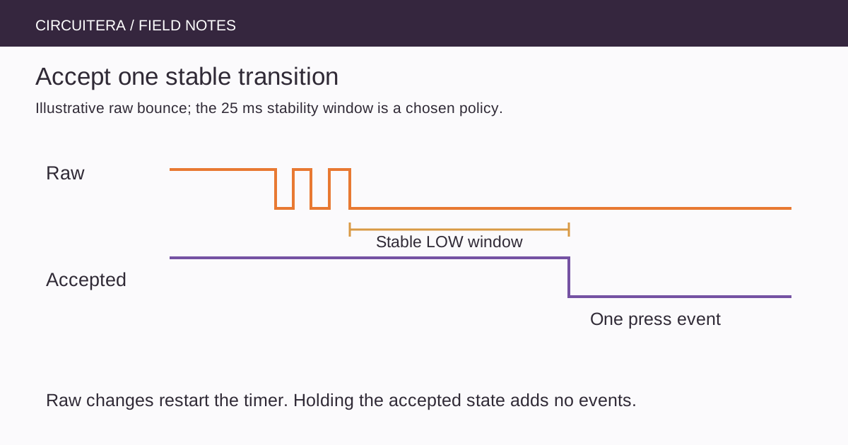
The raw input is the level sampled now. The candidate state is the most recently observed level while the program waits to see whether it persists. The accepted state is the level that has survived the chosen stability interval. Only a change in the accepted state should drive the event counter.
Without these distinctions, a sketch often compares two raw samples and calls every change a new press. That is edge detection, but it is not necessarily debounce. Conversely, a sketch can debounce the level successfully and still count continuously while the button is held if it never distinguishes an edge from a sustained state.
Wire a known active-low input
For the Uno R3 example, connect D2 to one side of a switch and the other side to GND, then enable INPUT_PULLUP. A four-terminal tactile button usually contains connected pairs of legs; establish which terminals are already joined before placing it across a breadboard gap. A permanent LOW is a wiring clue, not proof that the filter interval is too short.
Do not configure D2 as an output and connect it directly to ground. The circuit here is a low-voltage logic input. Long cables, industrial wiring and noisy installations may require an appropriate external interface beyond this simple educational example.
const byte buttonPin = 2;
const unsigned long stableFor = 25UL;
bool candidate = HIGH;
bool accepted = HIGH;
unsigned long changedAt = 0;
unsigned long presses = 0;

void setup() {
  pinMode(buttonPin, INPUT_PULLUP);
  Serial.begin(9600);
  candidate = accepted = digitalRead(buttonPin);
  changedAt = millis();
}

void loop() {
  const unsigned long now = millis();
  const bool raw = digitalRead(buttonPin);
  if (raw != candidate) {
    candidate = raw;
    changedAt = now;
  }
  if (candidate != accepted && now - changedAt >= stableFor) {
    accepted = candidate;
    if (accepted == LOW) {
      ++presses;
      Serial.println(presses);
    }
  }
}
Open Serial Monitor at 9600 baud. The code prints only accepted HIGH-to-LOW changes, rather than every loop pass or every raw edge. There is no deliberate wait inside loop(), so other short cooperative tasks can run alongside the filter. The output is a count, not a measurement of the switch's physical bounce duration.
Follow a noisy transition by hand
Imagine a released HIGH input that alternates LOW, HIGH and LOW within several milliseconds. Each raw change replaces the candidate and restarts changedAt. The accepted state remains HIGH until the final LOW persists for at least the stability interval. At that point the program accepts one press.
A held LOW does not produce more events because candidate equals accepted. The release must itself settle to HIGH before a later press can create another accepted falling edge. Writing those steps on paper is a better first debugging exercise than changing every comparison in the sketch at once.
Choose the interval for the actual interaction
The example uses 25 ms as a starting policy, not a universal switch specification. A longer interval rejects longer disturbances but delays acceptance and can reject intentional short taps. A shorter interval responds sooner but admits more unwanted transitions. Evaluate the real component, expected user behavior and electrical environment before settling on a value.
A signal pulse shorter than the stability interval is intentionally rejected by this algorithm. That makes it unsuitable as a generic pulse counter or fast encoder decoder. A rotary encoder has a sequence of related channels; filtering each as an unrelated pushbutton can destroy information about direction and movement.
Timing still depends on loop responsiveness
Unsigned elapsed-time subtraction handles the normal millisecond-counter wrap when timestamps and intervals use appropriate unsigned types and checks occur frequently enough. The code does not need to predict the next absolute deadline. The existing millis article explains that arithmetic in more detail.
The filter can only react to levels it actually samples. A blocking sensor call or a large serial transfer elsewhere in loop() can hide a complete press. Raising the baud rate might reduce one bottleneck, but it does not prove a maximum response time. Measure or reason about the longest loop path if missed input matters.
Define startup and reset behavior
This sketch initializes both candidate and accepted from the pin's current level. A button already held during startup is therefore treated as the starting state, not a newly accepted press. That is a deliberate interaction choice. If a product must act on a held-at-boot button, define a separate startup action instead of accidentally relying on variable initialization.
The count lives in RAM and returns to zero after reset. Saving every accepted press to EEPROM is a different persistence requirement with endurance implications. The EEPROM guide explains why an explicit save boundary can be preferable.
Diagnose before adding a second filter
If counts still double, inspect raw wiring, accepted-state transitions and whether another code path also increments the count. If nothing counts, verify that the input reaches LOW, persists long enough and returns HIGH between presses. Use a minimal switch circuit and the Circuitera IDE before integrating the filter into a large project.
The useful result is one explicit policy for accepting input, with known latency and limitations. Compilation validates the example's source; a simulator can illustrate a state sequence, but only actual observations characterize the bounce and interference of the hardware on your desk.
Sources and verification
Technical references were reviewed for this article. Board behavior is scoped to the named core and profile; follow a component’s actual datasheet when wiring hardware.