

Automatic Night Light
Use an LDR divider and two thresholds to turn on a light without chattering at one boundary.
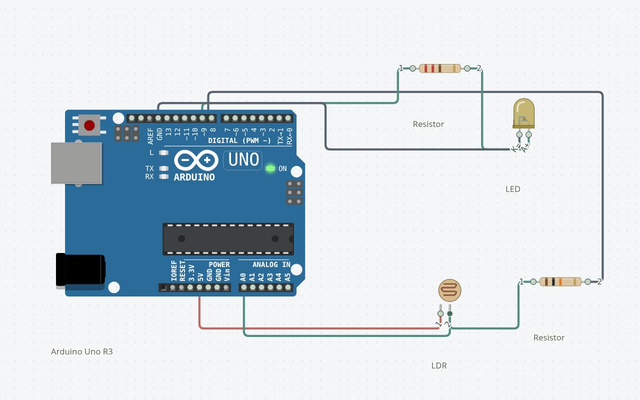
Wire it up
Disconnect power before changing connections. Follow terminal names rather than wire colors.
| From | To | Why it matters |
|---|---|---|
| LDR (sensor1) · 1 | Uno · 5V | Power connection |
| LDR (sensor1) · 2 | Uno · A0 | Match this terminal to the sketch |
| LDR (sensor1) · 2 | Resistor (divider) · 1 | Match this terminal to the sketch |
| Resistor (divider) · 2 | Uno · GND.2 | Ground reference |
| Uno · 9 | Resistor (r-led1) · 1 | Match this terminal to the sketch |
| Resistor (r-led1) · 2 | LED (led1) · A | Match this terminal to the sketch |
| LED (led1) · C | Uno · GND.1 | Ground reference |
The complete sketch
bool on = false;
void setup() { Serial.begin(9600); pinMode(9, OUTPUT); }
void loop() {
  int light = analogRead(A0);
  if (light < 350) on = true;
  if (light > 450) on = false;
  digitalWrite(9, on);
  Serial.print("light:"); Serial.println(light);
  delay(50);
}
The launch buttons use this same code and a matching saved circuit.
Build it step by step
Open a complete project
Launch in Simulator creates a separate Uno sketch and its matching wired circuit. Existing sketches are preserved. Press Run to compile and execute.
Explore the live circuit
Increase the LDR resistance above 20 kΩ to turn the LED on, then reduce it below 10 kΩ to turn it off.
Try it on hardware
Disconnect power while wiring. Match terminal names in the table, select the exact board, Verify, then connect and upload. Check component ratings and power requirements first.
Understand the sketch
Hysteresis
Below 350 the light turns on; above 450 it turns off. Between the thresholds it keeps the previous state. With this divider, a larger LDR resistance means a darker reading.
If something is different
Thresholds do not match a room
The model uses adjustable resistance, not lux. Calibrate real readings for the actual sensor and divider.
Expected output and tested scope
The LED turns on in the darker modeled condition and off in brighter conditions, using hysteresis to avoid chattering.
Version 1 · Last source- and build-matched test: 2026-10-25. Actual shipped AVR-GCC WASM compilation and Uno AVR engine execution; no physical hardware test.
Supported tutorial target: Arduino Uno R3 / ATmega328P. Compile: PASS · Modeled execution: PASS. Other boards require a separate review of pins, voltage, libraries and the exact build profile.